|
| | Make your own front 4 wheel drive axle? |  |
|
+4Destructive mr.modified TheBeal prancstaman 8 posters | |
| Author | Message |
|---|
prancstaman
Veteran Member

Join date : 2015-02-02
Points : 5096
Posts : 1412
Location : Cleveland,Ohio
 |  Subject: Make your own front 4 wheel drive axle? Subject: Make your own front 4 wheel drive axle?  April 20th 2019, 2:02 am April 20th 2019, 2:02 am | |
| Hay People,
It's late, trouble sleeping, so I'm doing this. Decided what kind of 4X4 I will be building, will be using the gearbox I am building too. So this topic goes with the "Make your own transmission" topic. So, I will be making a 4X4 riding mower for plowing my driveways and using this same rig for trail riding also. Only way to justify the expense is to use it for plowing in the winter time. Duel purpose. I can't just build a toy, well not yet anyways, that will be later, parts are stored and gathering, LOL. I'm doing these topics on the separate parts first, then will do the riding mower build when I get these parts done. Figure the separate topics would be easier to see then have them lost in a build thread. Anywho.........
More about the main build I will be doing. I want a 4 wheel drive riding mower. Probably no suspension. I said probably because that just adds complexity to the main build. If I do put suspension on this project, it will be on the rear only. The front having suspension is pretty much useless for me on this since it will be carrying a heavy plow in the winter time, but rear suspension will keep my back from hurting which will be something like a triangulated 4 link for mad flex in the rear. Seems pretty simple enough for that.
OK, back on topic. What I want. I want this front axle strong, real strong. I'm talking around 1 1/2 inch thick hard steel axle strong, with around 45 degrees or more of turning on this axle, The more, the better, the more fun it will be, especially when drifting in the snow. Open diff and locked diff (both) possibly. Seen a thread on that one here somewhere about the subject and theory. Just need to find a big enough diff but not too big that it takes 20 hp just to turn it. We shall see on that. Might be just a spool for this front axle. I'll see what I can find at the junk yard (Pull a Part). More on the turning part, that is 45 degrees or more of turning from going straight. Yes, total turning, well should be, 90 degrees or more of turning from lock to lock. Only way you can do that is from a CV axle joint. I got 2 CV axles from a car just sitting in the basement doing nothing for about 10 years now. I will get the exact angles from the turning motion but I am pretty sure that it is 90 degrees of full movement before they bind up from one way to the other. If they ever wear out, LOL, new reman one's are around $100 each or $45 at the junk yard. Bearings can be the OEM one's from the car or whatever I decide to use that is automotive which is pretty cheap and easy to get also. The axles are from an 1988 Delta 88 with a 3800 engine. That's a 150 hp engine in a 1.5 ton car, I think the axles will handle anything from the riding mower I throw at it, LOL.
I think I'll be covering the rear axle in this topic also. I'll pretty much go to the junk yard and yank out an axle from a 3/4 or 1 ton truck. Yup, live rear axle or spooled axle or how ever you want to say it. I probably will call it a spooled axle since it will be coming out of a truck, LOL.
That's pretty much the outline of this topic. I'll be using automotive parts pretty much because of the huge gain in strength and the ease of getting the stuff. The parts I will need for building this front axle, if I get from an ATV or other riding mowers would be just too weak for what I expect from the parts. Plus are not cheap unless I buy used and would probably be junk anyways, and too hard to get anything along these lines.
I'll be making all of the frame work, spindles, steering stuff, suspension links (rear) too. Some of this stuff I'll be making might not be in this topic. Keep an eye out for them, LOL. Pics on the parts that I have already will be in a day or so.
OK, I'm tired now. Later, it's past my bedtime, LOL. | |
|   | | TheBeal
Veteran Member


Age : 30
Join date : 2013-06-06
Points : 5717
Posts : 1402
Location : Central PA
 |  Subject: Re: Make your own front 4 wheel drive axle? Subject: Re: Make your own front 4 wheel drive axle?  April 20th 2019, 8:24 am April 20th 2019, 8:24 am | |
| 1 11/2 for the axle eh? I think that may be a bit overkill.
Id given some momentary thought to a 4x4 using a set of Jeep axles narrowed down. It would be a rather heavy thing, not something you could just toss in the bed of a truck. | |
|   | | prancstaman
Veteran Member


Join date : 2015-02-02
Points : 5096
Posts : 1412
Location : Cleveland,Ohio
 |  Subject: Re: Make your own front 4 wheel drive axle? Subject: Re: Make your own front 4 wheel drive axle?  April 20th 2019, 4:15 pm April 20th 2019, 4:15 pm | |
| - TheBeal wrote:
- 1 11/2 for the axle eh? I think that may be a bit overkill.
Id given some momentary thought to a 4x4 using a set of Jeep axles narrowed down. It would be a rather heavy thing, not something you could just toss in the bed of a truck. Yup, overkill. I like the term bullet proof though. Jeep axles, the whole thing, are too big. Even the small jeep axles would take alot of hp to turn, and are shaft drive. I got Jeep axles just sitting in my basement Dana 30, Dana 44. Just too big, even if they are narrowed. I'm thinking just using the CV joints, axles, and bearings. Should be about 30 lbs heavier then a AWS with transaxle, for comparison. Those AWS units are not light to begin with. I think that's a good point you made. I have that F/N/R rear steer setup from my riding mower still stored, that thing is built with cast knuckles, tubes, big bearings, and such. I could do a weight comparison. You get tired of breaking axles at some point. I want something built to last a very long time. Should fit in my truck when done, hopefully. Chevy Avalanche. Under 4 feet wide. | |
|   | | prancstaman
Veteran Member


Join date : 2015-02-02
Points : 5096
Posts : 1412
Location : Cleveland,Ohio
 |  Subject: A little mock up on the front axle Subject: A little mock up on the front axle  April 22nd 2019, 11:36 pm April 22nd 2019, 11:36 pm | |
| Hay People, I managed to grab some pics. Did a little mocking up and measuring of the parts. Not as stout as I thought but still will be bullet proof. The measurements of the parts are just a little bigger then the average parts for a riding mower, which means there is enough meat on the parts to carve down to something if needed. Even if the automotive parts are the same size, you would think that the steel they are made from would be a better or stronger steel. I hope anyways, LOL. If not, atleast it will have the CV joints, which are way better then U joints. U joints got there limits of 15 degrees before you start breaking them. And the whole speeding up and slowing down thing (phasing) adds to not a good idea thing, or something along that line. Lets start out with the measurements. The axle shaft itself is just over 1 inch diameter. If I need to, I can mill the axle shaft middle down to 1 inch to put a split hub on there, and a key way too. That is if I want to use just the one axle shaft to connect both CV joints. This would be a live axle then, or another name would be a spooled axle. What ever you want to call it, looks like it will be hard to actually turn, if I go this route. Would be the easiest way to build this though. 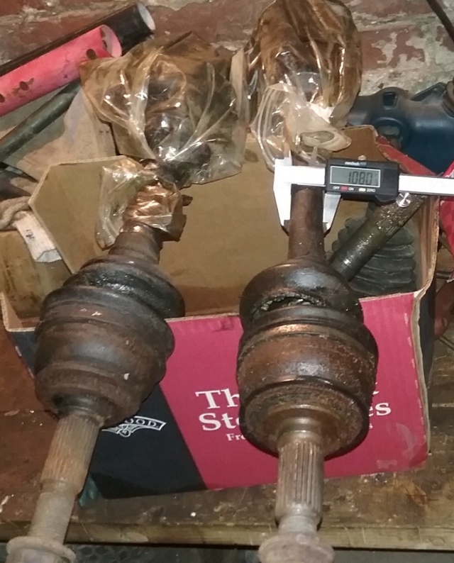 This is the end where the hub/wheel goes on. Just over 1 1/8 inches. I could buy some bearings with the 1 1/8 inch inside diameter. Then mill the CV joint end down to that and use a go cart hub on the end to hold it all together, maybe. Or get a couple of those bearing/hub assemblies from the car to use and fit a rim on somehow. Either way would be easy to do. 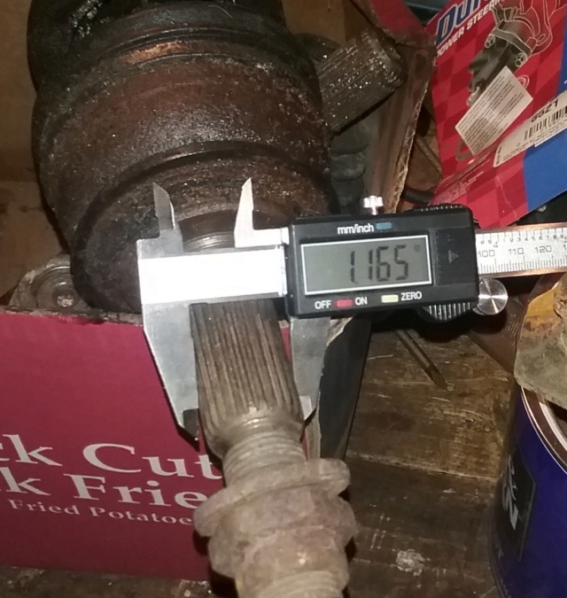 On the car, one CV axle is usually longer then the other. This one in the pic seems to be the longer one, so I measure it with a guess on how far it goes into the CV joint. Around 17 inches long. 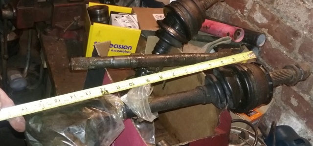 Then I measure the CV joint and guess where the pivot spot is. Around 6 1/2 inches. OK, the interesting thing about these axle shafts is the splines on both ends are the same. One possibility and would be the easiest way of doing this would be to use this longer axle and I can put a CV joint on both ends. The only difference of the ends of the splines are the slots for the retainer clips are in different spots, for the CV joint and the funny looking 3 prong U joint. I would have to leave the retaining clip out of one of the CV joints so the axle can float in and out of the spline on one end when turning. The CV joints themselves would be locked into the spindle housing like on the car, using the center nut to hold them, the bearings, and hub together. I figure with the 17 inch axle and two 6 1/2 inch CV joints put together as a unit, the axle assembly would be around 30 inches wide. Not to bad. 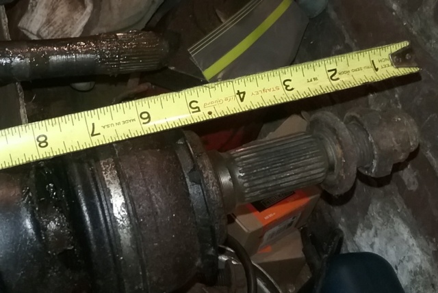 At this point, I am just playing around. I grab a set of front 6 inch rims and lay them down where I think the outcome of how wide the axle would be with a set of rims on it. 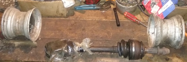 Measure it up at around 34 inches wide with the 6 inch rims. Will be wider with the 8 inch rims I'll probably be running.  Need a way to mount the rim to the hub. Might weld the rim to the hub, cut out the center to get access to the CV joint center nut and bolt the hub to the CV joint axle through the bearing. Using the big nut to hold the rim on too. Formula One style. Rim will be way out from the pivot point of the CV joint. Doing this makes it harder to steer. On front wheel drive cars, they put the pivot point in the center of the tire to make it easy to steer. This also could put strain on the wheel bearings, but how light the riding mower will be, I think it won't even be a factor.  In this pic, I bent the CV joint all the way over. I then upload it to my computer and run it through my windows paint program to draw the red lines. Lay a protractor on the screen and come up with this degree angle in the pic. If you do the math it pretty much comes out to 48 degrees from being straight. So, from all the way from one side and bent all the way over to the other side, that is 96 degrees of travel. Probably won't be able to take advantage of this but OVER 90 degrees of turning ability no matter how I build this axle setup sounds pretty good to me. 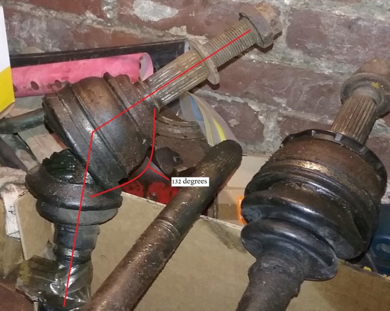 Last pic. What I was thinking about with the 2 CV joints on one shaft, on how it would kinda look like. These CV axles look pretty rough but the reason why I kept them was because they are remaned axles that was on the car about 6 months when I stripped the car. They still feel tight, like new still. Just need to replace the boots, clean out the old grease and repack them. Looks like some rust in there too but a little sandpaper would fix that. Be good as new. These axles and CV joints come completely apart so no problem cleaning them.  I'm liken what I am seeing. Already coming up with a plan on doing this. Next I will be disassembling these, cleaning the grease out of them, sanding the rust off, to see what parts I need to get to get these back to new condition. Might leave the grease out of them for now and keep then disassembled till I get more parts. All depends on what I can find at the junk yard. Never know, I might find the perfect differential with a good limited slip in it. Yah right, I'm not that lucky, LOL. Later.... | |
|   | | prancstaman
Veteran Member


Join date : 2015-02-02
Points : 5096
Posts : 1412
Location : Cleveland,Ohio
 |  Subject: The game plan is decided!! Subject: The game plan is decided!!  April 28th 2019, 1:54 am April 28th 2019, 1:54 am | |
| Hay People,
OK, made some executive decisions here. My plan for this will be to make this front 4 wheel drive axle with the automotive bearings that were made for the axles and a spooled axle shaft. It will be full time posi and the rig will be full time 4 wheel drive. Nothing fancy. That's as far as I am. Haven't decided on how to drive these axles yet. Either chain or belts. I don't know. Now I need to go get some wheel bearing/hubs from the junk yard off a car, which will be the next step.
Later.... | |
|   | | prancstaman
Veteran Member


Join date : 2015-02-02
Points : 5096
Posts : 1412
Location : Cleveland,Ohio
 |  Subject: Make your own front 4 wheel drive axle, parts gathering Subject: Make your own front 4 wheel drive axle, parts gathering  May 26th 2019, 9:18 pm May 26th 2019, 9:18 pm | |
| Hay People, Went to the junkyard and got a part, then to the part store for another part. Looked through the whole yard and could not find any wheel bearings off a car to fit the CV axles, looks like I'll have to buy new on these parts or just change CV axles to get what the junkyard has alot of. Either way, the prices would be about the same, so buying new bearings for the CV axles I already have seems better then buying all used parts. As long as the axle shaft spline doesn't strip I can change from a "88" Delta 88 CV joint over to like a "00" Grand Prix CV joint and bearing. The axle shaft splines and bearing mounting flanges are in the same locations, the thing that is different from car to car is the spline on the CV joint that fits in the wheel bearing/hub. The outside mounting dimensions are the same pretty much. I tested this theory with other parts I have from my kids car which was the Grand Prix. Good to know this, in the future when I need parts to fix my junk. OK, what I did find was an axle out of a Chevy 3500 van. This axle shaft will be milled down to something useful. 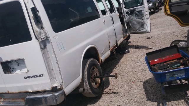 Will be the rear axle for the riding mower. Cost was $19.26, not too bad for a good hunk of solid steel shaft.  Almost 3 ft. long. Should be able to widdle something useful out of it.  I measure up the hub side of the axle. I can mill this side down to 1 1/4 inch diameter if needed. 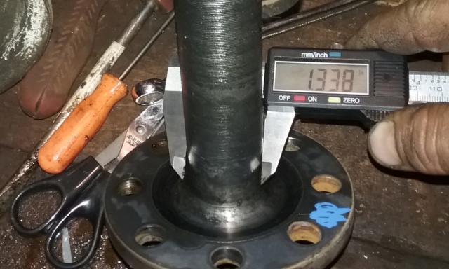 The spline side is bigger. Good to know.  I compare the van axle to a 3/4 inch go cart axle. Talk about apples and oranges. Should be stout enough, LOL. I'm thinking the final diameter of the riding mower rear axle shaft will be determined by what bearings I can get a hold of. I certainly am not going to pay $100 for 2 bearings of an oddball size. I'll look on McMaster Carr site or something like that for the rear bearings, but I'm thinking like 1 1/4 diameter will probably be the most likely outcome of this for the diameter of the rear axle shaft for mounting the rims on. The center of the axle can be whatever since I plan on making a split hub to mount either belts or chain too.  I lay all the parts out here. I went to the local Auto Zone for the CV boot. I already had one sitting on my frig for like 7 years for when I was working on another car, same part too. They are the boot kits, which come with the boot, grease, and clamps. Got it for $5 with my discount of $20 off. Then all the axles too. 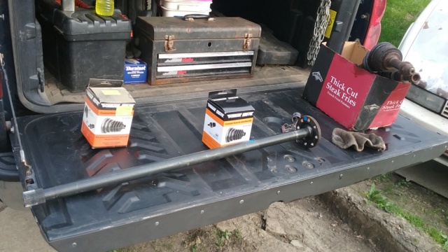 I got as far as disassembling the CV axles for cleaning. All the parts are layed out in the pan. The axle shaft on the edges of the pan is the longest at 18 inches and I fit the inners of the CV joints on both spline ends to show it can be done. Looking good so far. 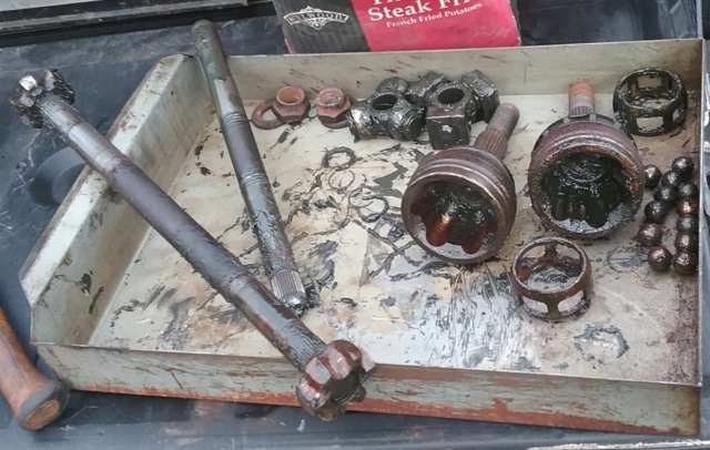 | |
|   | | TheBeal
Veteran Member


Age : 30
Join date : 2013-06-06
Points : 5717
Posts : 1402
Location : Central PA
 |  Subject: Re: Make your own front 4 wheel drive axle? Subject: Re: Make your own front 4 wheel drive axle?  May 27th 2019, 9:11 am May 27th 2019, 9:11 am | |
| - prancstaman wrote:
- TheBeal wrote:
- 1 11/2 for the axle eh? I think that may be a bit overkill.
Id given some momentary thought to a 4x4 using a set of Jeep axles narrowed down. It would be a rather heavy thing, not something you could just toss in the bed of a truck.
Yup, overkill. I like the term bullet proof though. Jeep axles, the whole thing, are too big. Even the small jeep axles would take alot of hp to turn, and are shaft drive. I got Jeep axles just sitting in my basement Dana 30, Dana 44. Just too big, even if they are narrowed. I'm thinking just using the CV joints, axles, and bearings. Should be about 30 lbs heavier then a AWS with transaxle, for comparison. Those AWS units are not light to begin with. I think that's a good point you made. I have that F/N/R rear steer setup from my riding mower still stored, that thing is built with cast knuckles, tubes, big bearings, and such. I could do a weight comparison. You get tired of breaking axles at some point. I want something built to last a very long time. Should fit in my truck when done, hopefully. Chevy Avalanche. Under 4 feet wide. Have you seen those videos on you tube of some 4x4s powered by a 212 predator? There doesnt seem to be any that show how well they would perform offroad, but they do move. The one was in a Dodge d50, it looked like it would move pretty well. The other one, there is a video of it pulling a semi truck. I figure there would be some hope, using a bigger engine, and it being a lighter vehicle. 20mph might not be too far of a stretch. Thats plenty fast enough o have some fun. | |
|   | | prancstaman
Veteran Member


Join date : 2015-02-02
Points : 5096
Posts : 1412
Location : Cleveland,Ohio
 |  Subject: Re: Make your own front 4 wheel drive axle? Subject: Re: Make your own front 4 wheel drive axle?  May 27th 2019, 12:03 pm May 27th 2019, 12:03 pm | |
| Yes ,seen them vids with the 212's running the 4x4's. Geared really high to be able to do it to. I'd be happy with 15mph to plow out my driveway. Probably won't use it too much for offroading. My wife will be driving this rig. She only needs to keep up with me in the Scorpion, and that is geared for 15mph right now also. Just starting out, will build better and faster later. | |
|   | | prancstaman
Veteran Member


Join date : 2015-02-02
Points : 5096
Posts : 1412
Location : Cleveland,Ohio
 |  Subject: Cleaning the parts Subject: Cleaning the parts  June 15th 2019, 12:51 am June 15th 2019, 12:51 am | |
| Hay People, Had a chance to clean most of the parts for the CV axles. I scotch brite the rust off of the inner parts of the CV joints. Then wire brush the outside of the CV joints. Still got some work to do on cleaning but that isn't what this post is about. Upon cleaning, I discovered something about the parts I think worth sharing. I bought both axles for the car as remanned axles. I figured out that one axle is rebuilt and the other axle is remanufactured, no big deal because they both felt new and they moved the car. There is a difference between the words and what is done though. Figured it was worth sharing about. So, rebuilt means that someone disassemble the part in question to inspect and replace only the bad parts. And remanufacturing a part means someone disassembles a part and regrinds the parts or replace all the parts with new parts except the main housing, to bring the part to like new tolerances. That is what the difference is. Remanufacturing is just a little better then rebuilt in some cases, but that's my opinion. Concerning these parts in question though, I thing they are the same quality, no big deal. So when I reassemble the CV joints, I can't put parts from one CV joint into the other CV joint because they have different size parts from the remanufacturing process. One joint's parts was reground to bring the tolerances up to like new condition. The other seems to have one part changed to bring it up to like new condition. And I'll be showing off my cleaning job too, LOL. Onto the pics........ I'll start with the ball bearings. A bit rusty in spots because of no grease on the spots. I just stuck a small wrench in a vise for something to place a ball bearing on to hold it while I rub it with a scotch brite. The scotch brite rubs off the shine on the surface but doesn't take off any metal like sand paper does, which is why I used a scotch brite pad (brown). When I reassemble the joints and are used, the surfaces will repolish themselves back to a mirror finish. Before and after pics of the ball bearings. 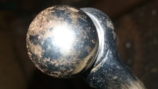  I do a measurement of the ball bearings to see if there is a difference in all the parts and discover that 6 ball bearings are around .020" bigger then the other 6. So some grinding of the main housing and inner ball bearing holder was ground down on one CV joint, which explains the 6 larger balls. The caliper is set to the diameter of the lower ball bearings to show the difference. 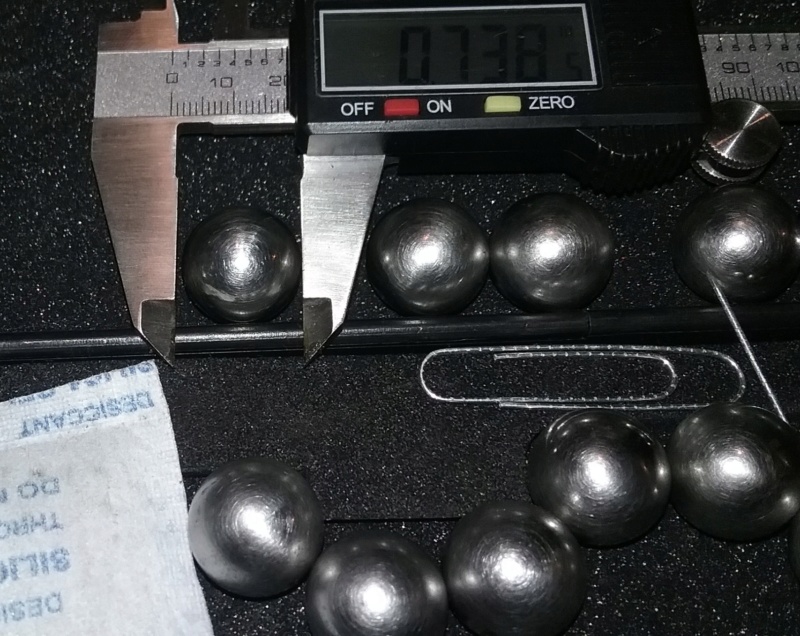 Look people, I found my marbles, well some of them anyways, LOL. All 12 cleaned. 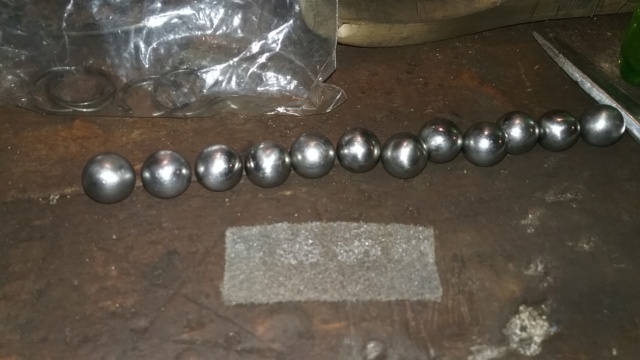 I wire brush the outside of the CV joints. Later I will take a flapper wheel to the rusty parts and paint them. 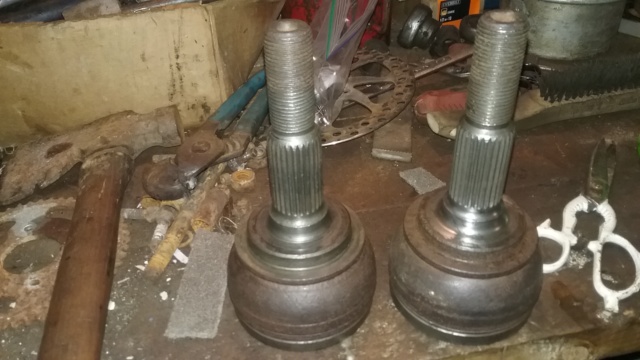 I scotch brite the insides to get the rust off. Takes some doing but get it done. I got the rust off the main surfaces which is what matters but getting the rust out of the centers was just impossible but all the loose rust is off. When I scotch brite these is where I noticed the difference in the parts. This is when I figured I should measure the parts up to see if there is a difference.  In this pic, the CV joint on the right is all original with no regrinding work. The CV joint on the left was ground down to accept bigger ball bearings, no clue on how many times they can regrind these but my guess is this one is 10 over. Which is .010" over original specs, I think is how you say it. 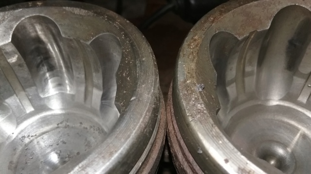 Here are the ball bearing holders, no clue what the actual name is but that is what I call them, LOL. One is ground down to match the other parts and one is original size. These are the parts that go on the splines of the axle shafts.  And finally, the ball bearing cages. They keep the ball bearings in a single orbit when the joint moves. I measure these up and they both are the same. 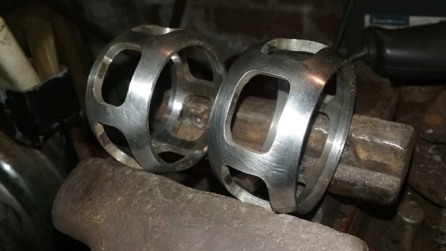 I'm pressing forward, no worries. Tonight I ordered new wheel bearings for this project. The bearings are wheel bearing/hub for an 1988 Delta 88 front wheel drive car. Should be strong enough and should last forever too. One of the main goals for this front axle setup is to last. I don't like building things that wear out after a couple uses. I want this to be able to out last the mower I put this on and be able to unbolt it and bolt it up to another mower (the mower will be expendable). Plus, be able to get parts when needed for servicing. Another reason, and I think is a very good reason is that the bearings being used off of a car is that these bearings can handle side to side thrust movements also. A regular roller bearing can't handle a side to side thrust, would damage the bearings and the races. I'll finish up the cleaning (boring). When the bearings get here, I need to figure out what size rim to use and how to mount the rims onto the bearing/hub. I seem to have a surplus of 8 inch rims I probably will be using for front and rear. I might even consider using a 6 inch rim but I like the 8 inch rim idea better. Don't want to go bigger because I don't like the look of a bigger rim and I don't have 4 of anything bigger, LOL. Later........... | |
|   | | prancstaman
Veteran Member


Join date : 2015-02-02
Points : 5096
Posts : 1412
Location : Cleveland,Ohio
 |  Subject: Little update on progess Subject: Little update on progess  July 13th 2019, 8:02 pm July 13th 2019, 8:02 pm | |
| Hay People.
Little update on progress to show I'm still moving forward on this. I ordered the bearings last month off Ebay, waited 2 weeks past the expected delivery date and still no parts (bummer). Filled a claim and got my money back yesterday. Too bad, I ordered parts before on Ebay and got them with no problem, even looked at the reviews which was mostly positive lately. So, I figured I give Amazon a try today. Price was still cheaper on Amazon then the local part store, little over half price while Ebay was under half price. Came to about $33 per bearing today. I don't mind paying that since they will probably last forever on this project. Ordering flanged pillow block bearings, needed 4, would come out to about the same and would have to mill the splines down on axle CV's to get them to work which would be an added expense.
So that's where I'm at. Should get bearings by the 22nd of this month, We shall see. I made sure it had the money back guarantee with it too, LOL. And if this don't work, there is always Rockauto, LOL. | |
|   | | mr.modified
Veteran Member


2015 Build-Off Top 3 Winner
2015 Build-Off Top 3 Winner
2016 Build-Off Top 3 Winner
2016 Build-Off Top 3 Winner
2018 Build-Off Finalist
2018 Build-Off Finalist
2022 Build-Off Entrant
2022 Build-Off Entrant
1st Place Build-Off 2014
1st Place Build-Off Winner 2014
2023 Build-Off Entrant
2023 Build-Off Entrant
Age : 34
Join date : 2013-11-02
Points : 7169
Posts : 2910
Location : New Jersey USA
 |  Subject: Re: Make your own front 4 wheel drive axle? Subject: Re: Make your own front 4 wheel drive axle?  July 14th 2019, 1:31 am July 14th 2019, 1:31 am | |
| Cool project. That's definitely the way to go if you want to make a 4wd setup for a tractor. Nice and rugged. If you wanted to bad enough, you could probably track down even smaller CV joints too. Should be cool to see it done! | |
|   | | prancstaman
Veteran Member


Join date : 2015-02-02
Points : 5096
Posts : 1412
Location : Cleveland,Ohio
 |  Subject: Re: Make your own front 4 wheel drive axle? Subject: Re: Make your own front 4 wheel drive axle?  July 14th 2019, 9:46 pm July 14th 2019, 9:46 pm | |
| - mr.modified wrote:
- Cool project. That's definitely the way to go if you want to make a 4wd setup for a tractor. Nice and rugged. If you wanted to bad enough, you could probably track down even smaller CV joints too. Should be cool to see it done!
Thanks. Yes, totally doable with smaller CV's. A quad with CV's could be used too for what I would imagine being the smallest, but would need the rest of the gear off the wheels too. Spindle bracket to hold the bearing, maybe brakes, tie rod ends, wheel hubs, and such. Could come up with your own by making them and use some riding mower hubs with some milling. Two important things I need to mention is, to do what I am doing on how I am doing it. 1- if using a single axle (like how I am doing) to use for both CV joints to attach to, The splines on both ends of the axle need to be the same for the CV joints to slide onto, them locking on the axle is a bonus. Using 2 axles would not matter since the axles would have the CV's on the ends as normal and then coupled or welded on the inside of axle part. 2- The CV joints need to come off the axle for servicing (like on my axles). This is important if you are using a single axle and putting on 2 CV joints. If using 2 axles then it would not matter because the CV joints can stay on the axle while coupling the 2 axles together. I figure I would mention this because on smaller cars, the CV joints do not come off the axles. I have no clue if the CV joints come off of quad axles for servicing or inspection. I might plan on taking apart the bearings also. I know the bearings off of the Delta 88 come apart easily with a press because I took one apart to clean the grease out of it and remove the seals to make a wheel balancer for my cars. Alot of the bearing/hub combo's, the bearing don't come apart, like on a Dodge pickup front bearing/hub combo. All depends on how you plan on attaching the rim to the hub. I might weld the rim to the hub of the bearing and only way to remove the rim would be taking apart the bearing. Some cars are like that to get the rear drum off, like a Focus. Might come in handy to know, LOL. If you go to a auto salvage yard to find parts, you can take apart both axles at the yard and piece together 1 axle with all the parts on it. When paying for it, you will only get charged for 1 axle since you built the axle at the yard, just don't tell the cashier what you did, LOL. You would walk out of the yard with 1 axle and 2 bearings instead of 2 axles and 2 bearings. Probably would save $50 doing it that way as long as the CV joints come off the axles. I could go to pull apart and get a single CV axle for $32 and 2 wheel bearings for the CV axle for $20 each. The axle setup off a different car, like a newer car of similar parts, with me building the axle in the yard and walking to the cashier after, for around $75. I would not know what the price of quad parts are to do this. Just looked up quad CV axles, cheapest one was $40 each and no clue if it is usable for this project. Knowledge of parts would be a must, which is why I'm using parts from an 88 delta 88. | |
|   | | prancstaman
Veteran Member


Join date : 2015-02-02
Points : 5096
Posts : 1412
Location : Cleveland,Ohio
 |  Subject: Got the bearings finally Subject: Got the bearings finally  July 20th 2019, 6:37 pm July 20th 2019, 6:37 pm | |
| Hay People, Finally got the bearings Friday.  Plus, they both are the right one's  Way to go Amazon!! 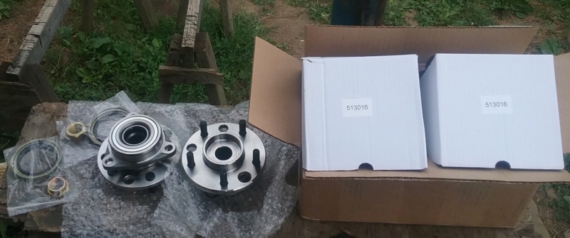  You get something like this in the mail, you just got to play with them, I mean see if they will work, LOL. So I do a little mocking up of the parts to see. I start with the axle shaft and the thingies on the ends.  I put the bearings on the CV's and lay the CV's in place.  I measure it up to see how wide this axle will be. From wheel hub to wheel hub is 25 inches. 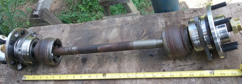 I set some 6 inch rims in place to get an idea how wide the outcome will be. 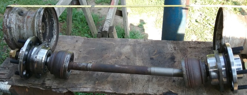 Measures up to be 33 1/2 inch's wide. I know, I see it too. Scrub radius is going to suck BIG time. I will try to get rid of some of that when making the spindle/bearing bracket, but yah, it's there and will suck.  Closer look of the ends. I plan on putting the joints right in the center of the CV joints, which will explain how there is going to be a very bad scrub radius. Why I will be doing this is because to drive this axle, ideally a chain drive would be best. To run a chain means that when the axle is turning, the shaft needs to stay put so the chain doesn't pop off the sprocket. Be the easiest way. If I put the joints closer to the wheels, then when turning, the axle shaft will pivot and move to the sides, not ideal for a chain driven axle. I would have to run a belt or 2 if the axle will be pivoting and moving to the sides when turning. 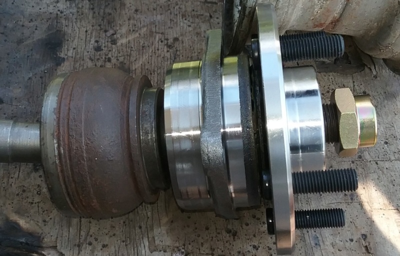 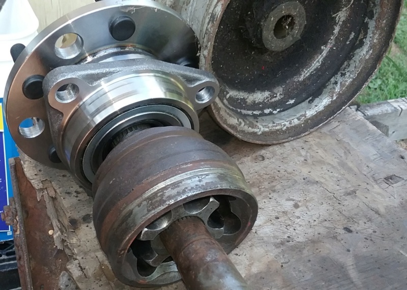 I measure up the width of my riding mower for comparison and comes to 34 inches in the rear and front in stock form. 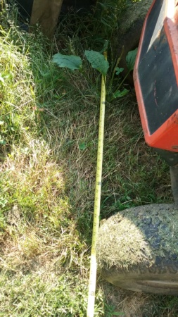 So, Running chain drive to the front and rear axles would be ideal. BUT, plan on having the rear with a 4 link and the front having a bad scrub radius, looks like the belt idea to drive the axles is looking better. Don't know if I will run twin belts per axle or twin belts on the front and a single for the rear, or single belts for both axles. We shall see on that one. Having a rear 4 link is more important then having a chain drive in the rear. I really don't want to run 1 chain and 1 belt either. Next move will be getting some rims on the front bearings. Things might change by doing that. 8 inch rims are pretty big. Should be interesting. | |
|   | | TheBeal
Veteran Member


Age : 30
Join date : 2013-06-06
Points : 5717
Posts : 1402
Location : Central PA
 |  Subject: Re: Make your own front 4 wheel drive axle? Subject: Re: Make your own front 4 wheel drive axle?  July 20th 2019, 7:20 pm July 20th 2019, 7:20 pm | |
| - Next move will be getting some rims on the front bearings. Things might change by doing that. 8 inch rims are pretty big. Should be interesting. wrote:
Im not sure the 8in wheels would seem big once the knuckles are built? | |
|   | | prancstaman
Veteran Member


Join date : 2015-02-02
Points : 5096
Posts : 1412
Location : Cleveland,Ohio
 |  Subject: Re: Make your own front 4 wheel drive axle? Subject: Re: Make your own front 4 wheel drive axle?  July 20th 2019, 7:29 pm July 20th 2019, 7:29 pm | |
| - TheBeal wrote:
Im not sure the 8in wheels would seem big once the knuckles are built? Yah, I know, only an inch more clearance all around then the 6 inch rims. LOL. And yah, When I build the knuckles, LOL. Couldn't figure out the name of that part, thanks, LOL. | |
|   | | prancstaman
Veteran Member


Join date : 2015-02-02
Points : 5096
Posts : 1412
Location : Cleveland,Ohio
 |  Subject: Front Rims Subject: Front Rims  July 22nd 2019, 10:51 pm July 22nd 2019, 10:51 pm | |
| Hay People, Sunday, at the end of the day, I went looking for some rims. I got MTD rims and regular rims. All had tires on them, and was hot, so I left them alone. Then I remembered I had a set of rims I cut up for the keyed centers for the brake rotors on my Scorpion. They was in my good junk box, so I dug them out. I cut these rims in half to get the centers out of them. No clue why I didn't throw them away, until now, LOL.  I grab a bearing and set the open half rim on. Almost the same size. That's something I can work with. Looks like the rim chokes down to almost the size of the hub. Be useful to center the rims on the hubs. 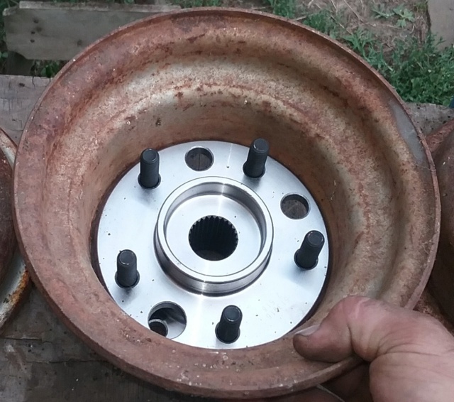 I flip the rim half over, place the bearing on a socket to hold it up while upside down, and put the other open half rim on top. I wanted to see how much room would be on the back half. Looks pretty open to me. 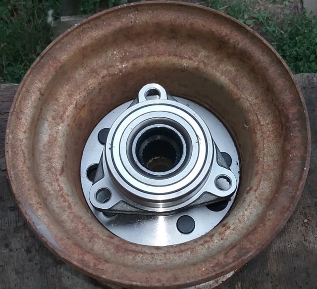 I work on the other 2 halves by finish cutting the centers out of them from the inside part of the rim. I used the corner for the cutter to follow. That worked for the most part.  The centers I just cut out was a 1/2 inch thick. 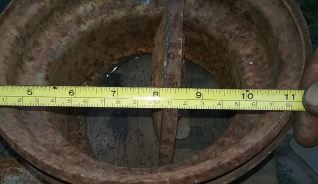 I then measure the rims 2 halves together to try to see how wide the rim is. 7 1/2 inches wide. Plus the 1/2 inch I cut out.  I measure the 2 rim halves that I cut 1 of the centers out to try to get an idea on how wide they use to be. I figure 8 inch wide rim, from lip to lip.  So, my plan is to weld the rim halves together with a new center in them so I can bolt them to the hub. I can do it anyway I need to since the rims are cut up already. Going to need the final width of these so I can match up the rears with them. I want all 4 rims the same width. I will probably be doing this to the rear rims also, since I will be making the rear axle. So when it get a little cooler, I will tear down another set of rims then. That's it for now, It's late and I'm tired. Later. | |
|   | | Destructive
Member


Age : 45
Join date : 2019-07-20
Points : 2022
Posts : 57
Location : King, NC
 | |   | | MightyRaze
Administrator


2017 Build-Off Finalist
2017 Build-Off Finalist
2018 Build-Off Top 3 Winner
2018 Build-Off Top 3 Winner
2019 Build-Off Top 3 Winner
2019 Build-Off Top 3 Winner
2021 Winner of Winners
2021 Winner of Winners
1st Place Build-Off 2022
1st Place Build-Off Winner 2022
10,000 POSTS!
10,000 POSTS!
2024 Build-Off Entrant
2024 Build-Off Entrant
Age : 49
Join date : 2016-09-06
Points : 15675
Posts : 10987
Location : Oklahoma
 |  Subject: Re: Make your own front 4 wheel drive axle? Subject: Re: Make your own front 4 wheel drive axle?  July 24th 2019, 2:40 pm July 24th 2019, 2:40 pm | |
| - Destructive wrote:
- Another case of proving my wife wrong with a "collection of parts" LOL
Hate to sidetrack... but be careful with those comments. LOL | |
|   | | prancstaman
Veteran Member


Join date : 2015-02-02
Points : 5096
Posts : 1412
Location : Cleveland,Ohio
 |  Subject: Re: Make your own front 4 wheel drive axle? Subject: Re: Make your own front 4 wheel drive axle?  July 24th 2019, 4:34 pm July 24th 2019, 4:34 pm | |
| - MightyRaze wrote:
- Destructive wrote:
- Another case of proving my wife wrong with a "collection of parts" LOL
Hate to sidetrack... but be careful with those comments. LOL Maybe it's not called hoarding if you actually use the stuff, LOL. | |
|   | | mr.modified
Veteran Member


2015 Build-Off Top 3 Winner
2015 Build-Off Top 3 Winner
2016 Build-Off Top 3 Winner
2016 Build-Off Top 3 Winner
2018 Build-Off Finalist
2018 Build-Off Finalist
2022 Build-Off Entrant
2022 Build-Off Entrant
1st Place Build-Off 2014
1st Place Build-Off Winner 2014
2023 Build-Off Entrant
2023 Build-Off Entrant
Age : 34
Join date : 2013-11-02
Points : 7169
Posts : 2910
Location : New Jersey USA
 |  Subject: Re: Make your own front 4 wheel drive axle? Subject: Re: Make your own front 4 wheel drive axle?  October 17th 2019, 10:06 am October 17th 2019, 10:06 am | |
| I was actually looking at some small cv axles on a car we had up on the lift the other day. Forget what brand but some of the smaller cars have ones that would be a good size for tractors. Your build should be pretty much indestructible. Have you gotten any further with it? | |
|   | | prancstaman
Veteran Member


Join date : 2015-02-02
Points : 5096
Posts : 1412
Location : Cleveland,Ohio
 |  Subject: Re: Make your own front 4 wheel drive axle? Subject: Re: Make your own front 4 wheel drive axle?  October 17th 2019, 8:34 pm October 17th 2019, 8:34 pm | |
| - mr.modified wrote:
- I was actually looking at some small cv axles on a car we had up on the lift the other day. Forget what brand but some of the smaller cars have ones that would be a good size for tractors. Your build should be pretty much indestructible. Have you gotten any further with it?
Yes, the smaller cars use smaller CV axle assemblies. I owned a Ford escort and did CV axle work on it but found out the CV axle joint itself was not serviceable. Meaning it would not come apart like these did in this thread. Only service that could be done on the CV's for the Escort was repack with grease and put a new boot on it, no disassembly on the CV joint itself. I'm sure it would be useable for something like this without taking apart the CV joint and knowing it was a good part. But would mean to cut up 2 of the same axles and need a way to connect the 2 together. Plus the actual bearings on the Ford was pressed into the spindle and I wanted something like a complete bearing unit that bolted in and ready to go kind of thing for ease of building. I used the CV axles in my basement out of convenience, knowing how they came apart completely and interchangeability of the individual parts and so on, and from experience of working on the cars helped out too. I'm at a stand still with all my toys at the moment. Blew the transmission in my Avalanche and in the middle of rebuilding it at the moment. No worries though, truck will be better then a Vette when done, LOL. A couple more weeks then will be back at it with my toys.  | |
|   | | mr.modified
Veteran Member


2015 Build-Off Top 3 Winner
2015 Build-Off Top 3 Winner
2016 Build-Off Top 3 Winner
2016 Build-Off Top 3 Winner
2018 Build-Off Finalist
2018 Build-Off Finalist
2022 Build-Off Entrant
2022 Build-Off Entrant
1st Place Build-Off 2014
1st Place Build-Off Winner 2014
2023 Build-Off Entrant
2023 Build-Off Entrant
Age : 34
Join date : 2013-11-02
Points : 7169
Posts : 2910
Location : New Jersey USA
 | |   | | prancstaman
Veteran Member


Join date : 2015-02-02
Points : 5096
Posts : 1412
Location : Cleveland,Ohio
 |  Subject: Figured out the target weight of the front axle assembly Subject: Figured out the target weight of the front axle assembly  December 28th 2019, 7:24 pm December 28th 2019, 7:24 pm | |
| Hay People, Had a few to do some work on this. Just one piece of the puzzle, is all. So, while the wife was sleeping, I grabbed the scale in the bathroom, LOL. Remember this thing?  This came out of my riding mower. It's an MTD unit. Features on it is as follows. Cast axle tubes and knuckles and axle tubes bolt to gearbox, heim joints, brake is internal, F/N/R only, bolt on hubs with rims and tires, and axles have a differential. This thing is pretty stout in itself. It's all I got to work with as a comparison. The other kind of all wheel steer units, I would assume is close in weight, just a guess though. I weigh one tire with rim first. 14 lbs.  This thing is heavy. 62.5 lbs.  So, as a complete assembly which includes everything in the pics comes to 90.5 lbs. I figure I can build my front axle assembly 30 lbs. heavier which I think is a reasonable goal I can meet with no problems by using automotive parts. So, my goal for the front 4 wheel drive axle assembly that will be able to bolt up to any frame will be 120.5 lbs. I also was looking at the rims for my setup. I should make a jig for welding the rims together so they turn out good. Something spinning at any speed should be true so it doesn't brake anything off, LOL. OK, that's it. | |
|   | | prancstaman
Veteran Member


Join date : 2015-02-02
Points : 5096
Posts : 1412
Location : Cleveland,Ohio
 |  Subject: First rim jig Subject: First rim jig  January 19th 2020, 1:33 am January 19th 2020, 1:33 am | |
| Hay People, So, I got to make some rims for this front end. Will be making all 4 but I don't know if all 4 rims will be the same. Back spacing might be different from front to back. I'll be focusing on the front rims for now. I'll talk about the rims first. Inside and outside halves are not the same, both differently shaped. The inside half rim is shaped to take the tire on and off, so this half has a wider smaller diameter for the whole rim itself. The outside half of the rim is a bigger diameter in a couple different spots and has the valve core hole in it. Well this is how I see the rim halves, Or you can look at it the other way but in all it doesn't matter. Options of the rims only matter for the application they go on. Since I got the rims cut up then I can rearrange these options how I need them. This pic shows what I mean about the different diameters. The inside rim half is on top and setting inside the bead area of the outer rim (bottom). And the inner side of the top rim half (which is the top of the pic) diameter is smaller. The smaller bead lip diameter and smaller diameter of the other end of this rim half is for putting the tire on and off. So the bead lips are shaped different to allow this. The inside bead lip is rolled inward to the center of rim while the outer rim half bead lip is rolled outward from the center for a larger bead lip diameter. Useful info to know, never realized this from rims. Hard to actually see when just looking at them.  The condition of these rims are in good shape. No dents, dings, rust holes, or being warped. I remember when I took them apart that the tires were the originals put on when they were made and I cut the tires off instead of using screwdrivers or hammers. Just a little rusty. Now how can I put these rims back together? Need a reference point that is the same on both rims even though the inside and outside halves look different. My reference point will be the bead area on the rims where the tire seals on the rims. I know any tire can be put onto any rim either way. The tire shop guy asks you "Do you want the white wall of the tires in or out?" Remember that one? I haven't seen a white walled tire in ages, LOL. Anywho, the bead of a rim is the "L" shape area on the ends where the tire contacts the rim and seals the air in. This next pic will show what I am talking about. Knowing through experience, alot of experience, that this bead area is identical inside and outside of any rim. I will base the makings of my jigs on this theory "The bead area is the same on the inside and outside of a rim". The tire bead also squares up the tire to the rim so the tire rolls true with the axle center line. The connection from the rim bead to the axle center line is the hub, more on the rim hub later. Bead area is outlined in the pic here. This area does not include the bead's lip area.  OK, onto making the first jig. The purpose of this first jig is to square up the rim halves using my reference point. I cut the rims apart free handed and the cuts are not straight so I need to recut the edges to be true. Further on down the road, I will also be using this first jig to cut apart a whole rim also, doing it right the first time with straight cuts. Got to start somewhere, LOL. I need a somewhat flat piece of steel for the base of the jig. I find a plate to mount a seat to in my junk pile. The holes are slotted for the seat bracket and I can expand on this. The googly eyes and Kool Aid smile will be explained in next pic, LOL.  The bolts (googly eyes) going threw the slots will rest on the bead area of the rim. The Kool Aid smile is the outline of the rim on the other end to make another slot in the center of the plate for a third bolt. The slots are for adjusting the bolts in the jig for different rims and also for different rim halves of the same rim, if needed. 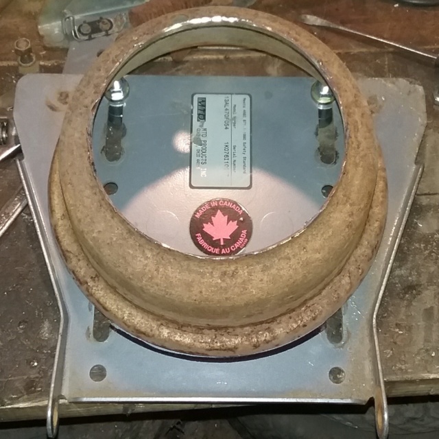 I want and need a couple more slots. Might as well make them all now since I got the tools out. I won't be using some of the slots for these rims but I will be keeping these jigs for other projects and just thinking ahead for that. Not too much slicing and dicing. Don't want to weaken the steel plate too much.  All slotted up and got the 3rd bolt in. Bolts slide up and down the slots for adjustability. I had to use really long bolts since that is all I had, which explains the spacers on the bolts. Shorter bolts can be used with washers also. So the rim's bead sits on the 3 bolts. 3 points of contact on the rim's bead. Would be too hard for 4 points of contact because of the rocking thing and too hard to adjust the rocking thing out. 3 points of contact on the rim's bead will always be sitting in the 3 points of contact. The spacers on the bolts ensure the bolt lengths are all even when tightened down. Also the bolts are lifting the rim off the surface of the steel plate so I'm not using the rims bead lip as a reference point that is not reliably true and also the steel plate surface is not perfectly flat either. The bolts use only the rim's bead area as a reference point.  While the rim is sitting on the 3 bolts, I will be spinning the rim by hand to cut it. While sitting on the 3 bolts, the rim slides side to side. So, brackets need to be made to get rid of this side to side movement of the rim and a couple more holes drilled into the steel plate to mount the brackets. I'll put the slots on the brackets this time. 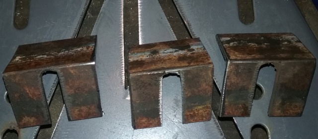  Here ya go. The 8" rim half is mounted in the jig by just sitting in it. I will be holding it in and spinning it on the bolts to make the cuts straight and true in reference to the rim's bead. 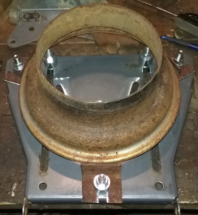 If you look real close, you can see the scratch marks on the bead area where the bolts slide on as a reference point.  OK, just playing around now for future use. I redo the bolts and brackets to see if I can actually mount a different rim in this jig. I grab a 6" front rim and am able to mount it in. This rim is pretty beat up on the bead lip but no big deal. I am still able to mount the 6" rim and spin it in the jig as is. 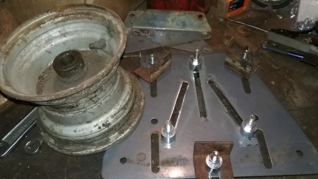 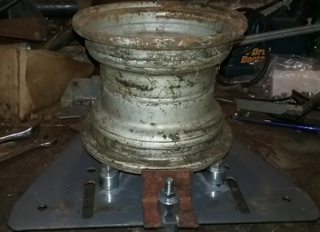 Now I have a way to hold the rim. Next is a jig to mount a hand grinder with a cut off wheel to cut the rims. I could just take the rims to my job and mount them in the lathe to true them up but what's the fun in that. Plus I won't be dependent on my job to work on my home projects. OK, it's past my bedtime. Later.......... | |
|   | | prancstaman
Veteran Member


Join date : 2015-02-02
Points : 5096
Posts : 1412
Location : Cleveland,Ohio
 |  Subject: 2nd rim jig Subject: 2nd rim jig  January 22nd 2020, 10:23 pm January 22nd 2020, 10:23 pm | |
| Hay People, The planets aligned so the goose layed her egg. Which gave me time to do some work on this, LOL. I need something to hold my hand grinder so I can true up the rims and cut rims up later on. I'm using my best hand grinder for this, the shaft doesn't wobble on it in other words, LOL. I pick through my best junk for this, the junk on the bench in other words. 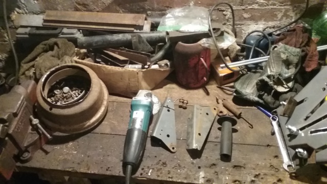 I mount the side handle on. Then grab the seat brackets and use one to fit it on the hand grinder, then slice it up to fit snug. The bolt on the bracket fits under the grinder handle for support. The hole next to the bolt is where I will mount the assembly to a rod and will swing into the rim. 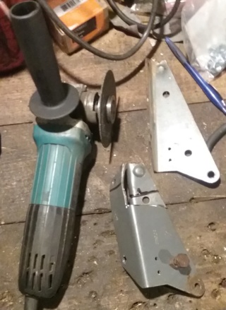 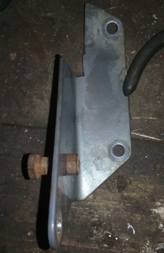 The side handle screwed on is the only thing holding the bracket on while the bolt up under the bracket is just there to help support the hand grinder under the handle. 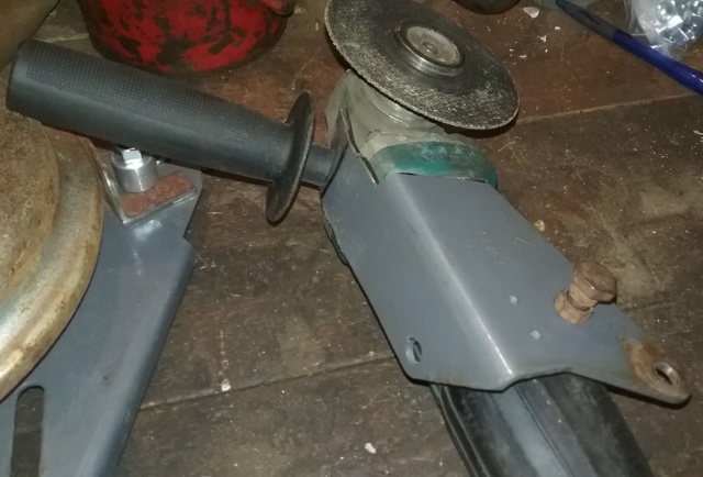 A better view of under the hand grinder handle with the bolt bolted to only the bracket. Should keep the hand grinder from vibrating while running. 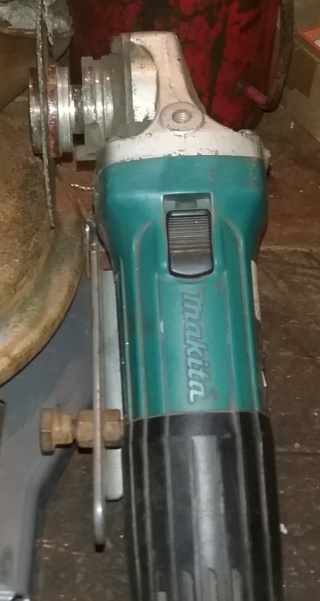 I will cut up a threaded rod for it to come up from the rim holding jig and will support the hand grinder with a cut off wheel, that will swing into the rim. Here are the pieces I use. A couple of alternator spacers, various size spacers and washers, a couple nuts, and a 13 inch long piece of threaded rod. 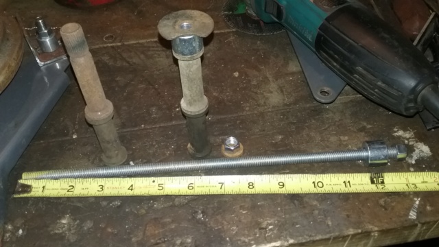 I piece it all together. The hand grinder will be able to be adjusted with it's height by rearranging the spacers, washers, and hand grinder bracket. When I tighten the threaded rod tight, I still can swing the hand grinder into the rim. The setup seems to be stable but with some effort the fixture will flex. Improvements on it will be later but for now and for the most part the assembly works. The threaded rod can be moved in different spots on the rim jig for different rims and I can also just drill another 3/8" hole if needed too. 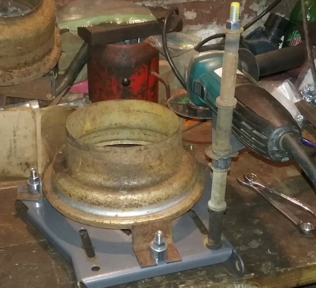 I do a test run now by just scribing a line in the rim all the way around. Worked pretty good. The rim jig needs to be mounted to something so it doesn't move to free up the hand holding it in place. Then I can use one hand to push the hand grinder into the rim and the other hand to spin the rim. For now, I set the cutoff wheel on the rim, turn the grinder on and spin the rim to make a mark all the way around. 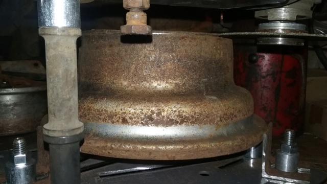 And the end result. Cool, it works, LOL. 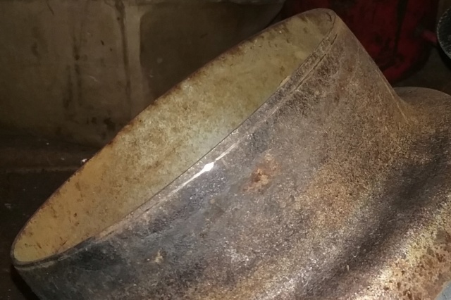 That's as far as I got for tonight. I'll true up the rim halves later. Even if these 2 jigs self-destruct doing these rims, this will give me experience and know how on doing it for improvements later. After I true up the rims, the next jig will be to roll up some flat stock steel to widen the rims some. I think you call it "Rim Banding". OK, that's it for now. | |
|   | | Sponsored content
 | |   | | | | Make your own front 4 wheel drive axle? |  |
|
Similar topics |  |
|
| | Permissions in this forum: | You cannot reply to topics in this forum
| |
| |
| | Who is online? | In total there are 85 users online :: 0 Registered, 0 Hidden and 85 Guests
None
Most users ever online was 412 on January 7th 2023, 7:59 am
|
|


