|
| | wiring up a modern key switch |  |
| | |
| Author | Message |
|---|
FOSWMT
Member


Join date : 2013-07-28
Points : 4331
Posts : 163
 | |   | | Doc Sprocket
Site VIP


2018 Build-Off Entrant
2018 Build-Off Entrant
2021 Winner of Winners
2021 Winner of Winners
1st Place Build-Off 2016
1st Place Build-Off Winner 2016
Age : 51
Join date : 2013-04-21
Points : 7320
Posts : 2914
Location : Ontario Canada
 |  Subject: Re: wiring up a modern key switch Subject: Re: wiring up a modern key switch  September 15th 2013, 3:05 pm September 15th 2013, 3:05 pm | |
| As far as I know, it will not work and here's why:
The magneto-based ignition systems used on OPE engines like our mower stuff need to COMPLETE the kill circuit to shut off the engine. When you switch one of these engines off using an original equipment switch, the coil primary is connected to ground via the switch. On the OFF position, the switch completes the circuit. In the ON position, there is no contact from the coil primary to ground.
In automotive or "powered coil" applications- the reverse is true. Turning the switch ON completes the circuit between the power and the coil, allowing it to energize. In the OFF position, there is no contact. As such universal key switches tend to not work on magneto engines. In short- a switch for a magneto engine needs to be normally closed (off position) whereas the switch for a powered ignition needs to be normally open (off position).
Now- if you have a different ignition system from what we usually deal with here, then the switch may work for you. | |
|   | | FOSWMT
Member


Join date : 2013-07-28
Points : 4331
Posts : 163
 | |   | | FOSWMT
Member


Join date : 2013-07-28
Points : 4331
Posts : 163
 |  Subject: this is my wiring Subject: this is my wiring  September 15th 2013, 3:35 pm September 15th 2013, 3:35 pm | |
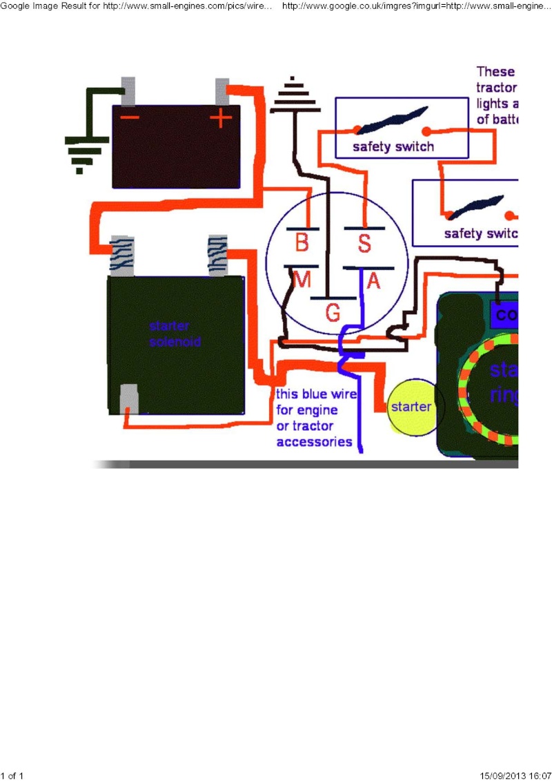
|  This is my wiring diagram. I am wondering if this can be made to work. Do you have a diagram that represents the internal switching in the ignition switch please? | |
|   | | Doc Sprocket
Site VIP


2018 Build-Off Entrant
2018 Build-Off Entrant
2021 Winner of Winners
2021 Winner of Winners
1st Place Build-Off 2016
1st Place Build-Off Winner 2016
Age : 51
Join date : 2013-04-21
Points : 7320
Posts : 2914
Location : Ontario Canada
 |  Subject: Re: wiring up a modern key switch Subject: Re: wiring up a modern key switch  September 15th 2013, 3:35 pm September 15th 2013, 3:35 pm | |
| No- you need a switch that COMPLETES a circuit in the OFF position, rather then opening the circuit like most do. | |
|   | | FOSWMT
Member


Join date : 2013-07-28
Points : 4331
Posts : 163
 |  Subject: Re: wiring up a modern key switch Subject: Re: wiring up a modern key switch  September 15th 2013, 3:39 pm September 15th 2013, 3:39 pm | |
| I am not sure I understand I am used to wiring cars but this is a bit differant I would be grateful of any help guidance you can give please? I hate the switch thats a basic install it has no security in it as a child could turn it on.
Internal wiring of the switch as a diagram might help | |
|   | | Stretch44875
Administrator


Age : 49
Join date : 2012-04-05
Points : 5703
Posts : 959
Location : Mansfield, Ohio
 | |   | | Doc Sprocket
Site VIP


2018 Build-Off Entrant
2018 Build-Off Entrant
2021 Winner of Winners
2021 Winner of Winners
1st Place Build-Off 2016
1st Place Build-Off Winner 2016
Age : 51
Join date : 2013-04-21
Points : 7320
Posts : 2914
Location : Ontario Canada
 |  Subject: Re: wiring up a modern key switch Subject: Re: wiring up a modern key switch  September 16th 2013, 9:19 am September 16th 2013, 9:19 am | |
| Good point, Stretch. I completely forgot about the possibility, and I should NOT have- because I've done it. (duh) | |
|   | | FOSWMT
Member


Join date : 2013-07-28
Points : 4331
Posts : 163
 | |   | | Doc Sprocket
Site VIP


2018 Build-Off Entrant
2018 Build-Off Entrant
2021 Winner of Winners
2021 Winner of Winners
1st Place Build-Off 2016
1st Place Build-Off Winner 2016
Age : 51
Join date : 2013-04-21
Points : 7320
Posts : 2914
Location : Ontario Canada
 |  Subject: Re: wiring up a modern key switch Subject: Re: wiring up a modern key switch  September 16th 2013, 9:33 am September 16th 2013, 9:33 am | |
| I think not (see all my previous comments). Try something simpler, like Briggs And Stratton, Toro, Craftsman, MTD, Lawn Tractor, etc. | |
|   | | FOSWMT
Member


Join date : 2013-07-28
Points : 4331
Posts : 163
 |  Subject: Re: wiring up a modern key switch Subject: Re: wiring up a modern key switch  September 16th 2013, 9:38 am September 16th 2013, 9:38 am | |
| I saw that Positive feed to coil . The trouble with all the ones you have mentioned is that they all use the same key | |
|   | | Doc Sprocket
Site VIP


2018 Build-Off Entrant
2018 Build-Off Entrant
2021 Winner of Winners
2021 Winner of Winners
1st Place Build-Off 2016
1st Place Build-Off Winner 2016
Age : 51
Join date : 2013-04-21
Points : 7320
Posts : 2914
Location : Ontario Canada
 |  Subject: Re: wiring up a modern key switch Subject: Re: wiring up a modern key switch  September 16th 2013, 9:42 am September 16th 2013, 9:42 am | |
| Yes, they tend to. Do you have a security concern?
I'll have a look up in the shop later. I know darn good and well I have a Briggs key switch unit that uses "proper" key design and tumblers like a padlock. If there's a part number on it, I will let you know. | |
|   | | FOSWMT
Member


Join date : 2013-07-28
Points : 4331
Posts : 163
 | |   | | Doc Sprocket
Site VIP


2018 Build-Off Entrant
2018 Build-Off Entrant
2021 Winner of Winners
2021 Winner of Winners
1st Place Build-Off 2016
1st Place Build-Off Winner 2016
Age : 51
Join date : 2013-04-21
Points : 7320
Posts : 2914
Location : Ontario Canada
 |  Subject: Re: wiring up a modern key switch Subject: Re: wiring up a modern key switch  September 16th 2013, 11:00 am September 16th 2013, 11:00 am | |
| Well, I dug up the ignition switch in question, and there's simply no discernible part number on it. Sorry. | |
|   | | TheRainbowBoxer
Moderator


Age : 49
Join date : 2012-04-23
Points : 5703
Posts : 1091
Location : Galion, OH
 |  Subject: Re: wiring up a modern key switch Subject: Re: wiring up a modern key switch  September 16th 2013, 11:40 am September 16th 2013, 11:40 am | |
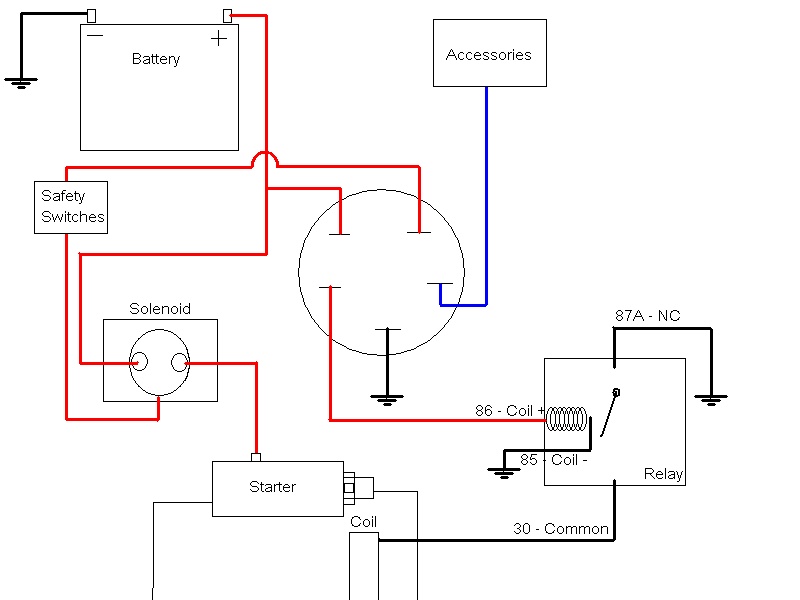
| As Doc tried to convey, the problem with most non-mower keyswitches is that they provide a 12 volt+ signal on the ignition wire when the switch is turned on. Putting 12 volts+ on the coil wire will likely cook the coil (I've done that). What the mower engine needs if for the coil wire to be open (nothing + or -) while it is running. To stop the engine, this wire needs to go to ground. I drew up a schematic for you, based on what you previously posted. This drawing shows a relay switching the polarity of the ignition to use as a kill switch, like most mower engines use. Please fully test the keyswitch pins' functions prior to using this diagram, as it assumes the functions of the pins as you drew them.  | |
|   | | redlinemotorsportts
Moderator


2014 Build-Off Entrant
2014 Build-Off Entrant
Age : 27
Join date : 2013-03-18
Points : 7485
Posts : 3131
Location : raleigh nc
 | |   | | FOSWMT
Member


Join date : 2013-07-28
Points : 4331
Posts : 163
 |  Subject: Re: wiring up a modern key switch Subject: Re: wiring up a modern key switch  September 16th 2013, 12:48 pm September 16th 2013, 12:48 pm | |
| - Doc Sprocket wrote:
- Well, I dug up the ignition switch in question, and there's simply no discernible part number on it. Sorry.
Thank you for looking its a shame it didnt have any marks as this is a simple route . I see The Rainbow boxer has given a relay way of using my purchased switch to drive the coil to ground . That is a brilliant sketch thank you so much for the time and effort you spent drawing it :-) I think the new switch will have differant modern positions . What I gave you was from the old ignition switch . Do you have a diagram to represent the switch internals so that I can use a meter to get the same pins when my switch arrives please. I am thinking from what has been said M -> GND on B ->S starter cranked released B->A Is this correct? | |
|   | | TheRainbowBoxer
Moderator


Age : 49
Join date : 2012-04-23
Points : 5703
Posts : 1091
Location : Galion, OH
 |  Subject: Re: wiring up a modern key switch Subject: Re: wiring up a modern key switch  September 16th 2013, 1:07 pm September 16th 2013, 1:07 pm | |
| Not sure how I'd diagram that, but I can go over the specific tests.
These tests would be done with no connections made, and using a multimeter on "ohms" or other continuity setting.
"should read open" for this example means no connection to 12 volt+ pin or Ground pin/switch case (on "ohms" meter will rest as if not touching anything)
With key in off position:
Accessory pin should read open
Starter pin should read open
Ignition pin should read open for "modern" ignition switch. (should connect to ground pin (and/or switch casing) on standard mower switch)
With key in on position:
Accessory pin should connect to 12 volt+ pin
Starter pin should read open
Ignition pin should read connect to 12 volt+ pin on "modern" switch. (or read open on standard mower switch)
With Key in start position:
Accessory pin will show open, or possibly connection to 12 volt+ pin.
Starter pin will show connection to 12 volt+ pin.
Ignition pin should read open on standard mower switch, or 12 volt+ pin on "modern" switch.
Its possible that the switch will not have a separate accessory pin or a ground pin.
| |
|   | | FOSWMT
Member


Join date : 2013-07-28
Points : 4331
Posts : 163
 |  Subject: Re: wiring up a modern key switch Subject: Re: wiring up a modern key switch  September 16th 2013, 1:13 pm September 16th 2013, 1:13 pm | |
| Thank you . You are correct the switch I have ordered is a 4 Position (Park/Off/On/Ignition). I presume this means it will not work either as I need an accessory feed as my existing switch has one? | |
|   | | FOSWMT
Member


Join date : 2013-07-28
Points : 4331
Posts : 163
 |  Subject: Re: wiring up a modern key switch Subject: Re: wiring up a modern key switch  September 16th 2013, 1:15 pm September 16th 2013, 1:15 pm | |
| - Doc Sprocket wrote:
- Well, I dug up the ignition switch in question, and there's simply no discernible part number on it. Sorry.
It is lucus though is there anyway it could be identified by a picture if you could post one ? | |
|   | | TheRainbowBoxer
Moderator


Age : 49
Join date : 2012-04-23
Points : 5703
Posts : 1091
Location : Galion, OH
 |  Subject: Re: wiring up a modern key switch Subject: Re: wiring up a modern key switch  September 16th 2013, 1:19 pm September 16th 2013, 1:19 pm | |
| No, you should still be ok... the accessory items in this case (assuming a 12 volt+ ignition) would just tie into ignition, rather than have their own pin.
Edited to add: Not sure what the "Park" position would be used for or how it would work | |
|   | | FOSWMT
Member


Join date : 2013-07-28
Points : 4331
Posts : 163
 |  Subject: Re: wiring up a modern key switch Subject: Re: wiring up a modern key switch  September 16th 2013, 1:54 pm September 16th 2013, 1:54 pm | |
| - TheRainbowBoxer wrote:
- No, you should still be ok... the accessory items in this case (assuming a 12 volt+ ignition) would just tie into ignition, rather than have their own pin.
Edited to add: Not sure what the "Park" position would be used for or how it would work Presumably could be tied to lights to flatten battery :-p | |
|   | | FOSWMT
Member


Join date : 2013-07-28
Points : 4331
Posts : 163
 |  Subject: Re: wiring up a modern key switch Subject: Re: wiring up a modern key switch  September 20th 2013, 5:59 am September 20th 2013, 5:59 am | |
| - TheRainbowBoxer wrote:
- As Doc tried to convey, the problem with most non-mower keyswitches is that they provide a 12 volt+ signal on the ignition wire when the switch is turned on. Putting 12 volts+ on the coil wire will likely cook the coil (I've done that).
What the mower engine needs if for the coil wire to be open (nothing + or -) while it is running. To stop the engine, this wire needs to go to ground.
I drew up a schematic for you, based on what you previously posted. This drawing shows a relay switching the polarity of the ignition to use as a kill switch, like most mower engines use. Please fully test the keyswitch pins' functions prior to using this diagram, as it assumes the functions of the pins as you drew them.
 Hi I have received my relay and wonder if your diagram is wrong you quote use of 87a which i think should be 87. Further I am curious about the earths can these be connected together and wired to the earth that comes to the switch please? Is NC 87a earth supposed to be floating and not connected to anything? I have made up switch like this:  | |
|   | | Doc Sprocket
Site VIP


2018 Build-Off Entrant
2018 Build-Off Entrant
2021 Winner of Winners
2021 Winner of Winners
1st Place Build-Off 2016
1st Place Build-Off Winner 2016
Age : 51
Join date : 2013-04-21
Points : 7320
Posts : 2914
Location : Ontario Canada
 |  Subject: Re: wiring up a modern key switch Subject: Re: wiring up a modern key switch  September 20th 2013, 8:29 am September 20th 2013, 8:29 am | |
| As I understand it, the whole point of using 87A is that it (earths) grounds when the trigger coil is de-energized with the switch in the OFF position- thus completing the path from the engine's kill wire (terminal 30) to ground (earth). Remember that the engine's kill circuit must be "closed" (completed, continous to earth) to shut down. Hence the need for the relay in the 1st place to use the "incompatible" key switch.
All Earths may be interconnected.
Please note that in order for the system to work, 12v must be maintained at the relay or the engine will not run. Ensure the relay is powered up before attempting to start. If, for example- you were to try and jump start engine by applying 12v+ directly to the starter terminal, engine will crank over but not fire unless you feed the relay coil 12v at the same time. | |
|   | | Ariens YT11
Established Member


2014 Build-Off Entrant
2014 Build-Off Entrant
2015 Build-Off Entrant
2015 Build-Off Entrant
Age : 27
Join date : 2012-10-31
Points : 5166
Posts : 745
Location : The Wyo-Braska Panhandle
 |  Subject: Re: wiring up a modern key switch Subject: Re: wiring up a modern key switch  September 20th 2013, 11:19 am September 20th 2013, 11:19 am | |
| - Doc Sprocket wrote:
- As I understand it, the whole point of using 87A is that it (earths) grounds when the trigger coil is de-energized with the switch in the OFF position- thus completing the path from the engine's kill wire (terminal 30) to ground (earth). Remember that the engine's kill circuit must be "closed" (completed, continous to earth) to shut down. Hence the need for the relay in the 1st place to use the "incompatible" key switch.
All Earths may be interconnected.
Please note that in order for the system to work, 12v must be maintained at the relay or the engine will not run. Ensure the relay is powered up before attempting to start. If, for example- you were to try and jump start engine by applying 12v+ directly to the starter terminal, engine will crank over but not fire unless you feed the relay coil 12v at the same time. I see a switch with a light in your future LOL, Also so you don't kill the batt when giving the relay 12v all the time. | |
|   | | Sponsored content
 | |   | | | | wiring up a modern key switch |  |
|
Similar topics |  |
|
| | Permissions in this forum: | You cannot reply to topics in this forum
| |
| |
| | Who is online? | In total there are 93 users online :: 0 Registered, 0 Hidden and 93 Guests
None
Most users ever online was 412 on January 7th 2023, 7:59 am
|
|


